Inspiring Smiles Forever
![]()
Complete Works, Portraits, Landscapes, Still Lifes, Sculpture, Lego Artist...
Sign up for yearly notices by sending an e-mail to newart-subscribe@tomlohre.com
Post comments on
https://www.facebook.com/artisthos/
Click here to see all the art created by Lego Painting Automata

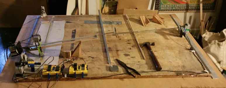
Mom & Dad with Susan, 36" x 24", pastel on 90lb paper, May 6th, 2003, this was printed with a random printer following a plate
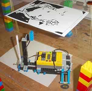
Randomly moving around the paper applying color when the above plate is black. The plate is turned upwards to illustrate what it looks like. When printing it is turned down so the light sensor can detect black and apply the color
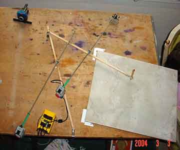
Instead of a XY table as a printer, the next printer will be a sweeping printer that will more quickly apply the color and suggest a human touch.

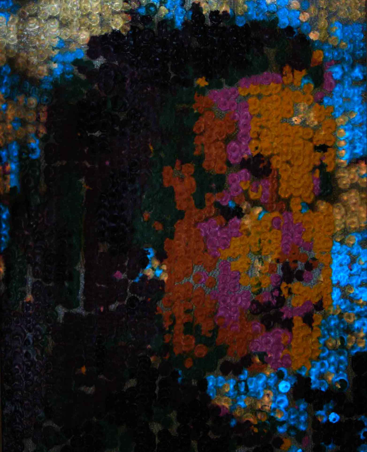
Helen, 8 x 10, Oil on canvas, printed using the sweeping printer
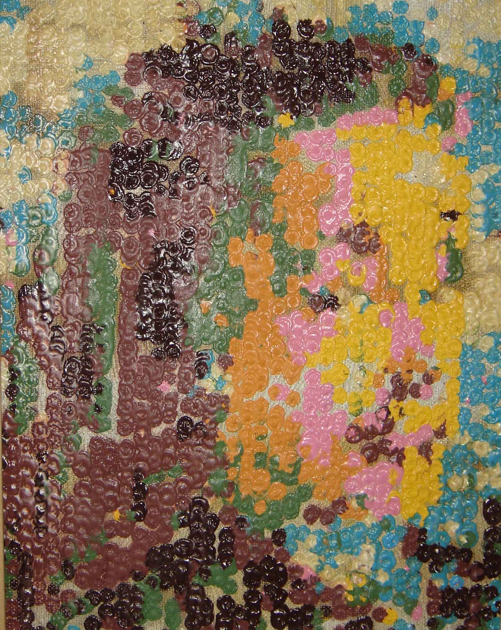
Irene, 16" x 20", August 2007
The first painting done by "Artisto" using glow in the dark colors makes use of a strong combination of colors for a powerful graphic effect. The sky comes to life in the dark. Two different glow in the dark colors, blue and orange, where used for the background.
The Cincinnati Post On-Line Story about the robot
170407 Using RCX bricks and RoboLab 2.94, in many ways is like being stranded on Mars and this is all there is, which is everything. There is plenty of time until the next spaceship arrives since contacting Earth depends on making this software and hardware work. The first space shuttle used a software and hardware that was more primitive than RCX bricks and RoboLab 2.94. The goal is to surf the Internet for a paintable image, change it into nine colors of blobs and print it by melting oil pastels on metal.
170331 Seeking a tutor who can help me apply posterization to images in RoboLab
2.94. Using posterization I simplify images for paintings.
I have been doing this in PhotoShop but want to be able to do it using the Threshold,
MorphOpen, MorphClose, MorphProperOpen, MorphProperClose, MorphThin and Invert
commands in RoboLab.
We would be exchanging emails as I work my way through programming with RoboLab
2.94.
It is very hard to find help in advance image work.
170314 Having to trouble shoot a Dell Inspiron 1100 not booting up cleanly. An alarm goes off and it goes to safe boot mode. I am running the original Home version of XP without updates and RoboLab 2.94. Keeping the 2007 working original program until new application arm is working. Side arm needs to come in and heat up surface where oil pastel dot is applied and move aside for the application wheel to rotate to the color and move down to apply the dot. Thinking it will be a side arm where the heating box flips down, moves into dot area for allotted time then out.
170204 The new painting machine to make the shrine portraits will be a larger
version of the 2007 machine. A small heating coil will be moved into position
over the metal surface to accept the oil pastel stick in a timely manner. A
weathering test is being done to see how the oil pastel paintings last outside.
A lot has been learned heating up the surface to melt the oil pastel sticks
on a hot surface since 2007. The technique has been used and developed almost
on a monthly basis since then. The process lends itself to en plien air work
and quick work and having the work look like oil paint becoming fully dried
as soon the oil pastel cools.
170203 This new machine will bring a disk down onto a surface of latex paint then move it to the work surface. Hopefully the surface tension will be enough to trigger a touch sensor activating raising up the disk and moving the paint to the working surface. There may be 3000 dots on the 24" x 24" metal canvas. Nine colors will be used and it may take several days to fill in the spaces since it will need nine passes because the paint will not dry quick enough to bring down the next color. It will be more permanent than the original printing machine that melted eight colors in sequence requiring one pass. I should do a test to the permanence first.
170201 The beginning of the next painting machine. Using paint, daubing a dot on a 24" x 24" piece of metal for the shrine portraits. Metal will prove to be more durable. Using Lego parts and the "get pixel" command to retrieve pixel information from an image, applying it to it's location. One complete pass may take 12 hours and nine passes, one for each color will be needed. The machine runs automatically and may work overnight.
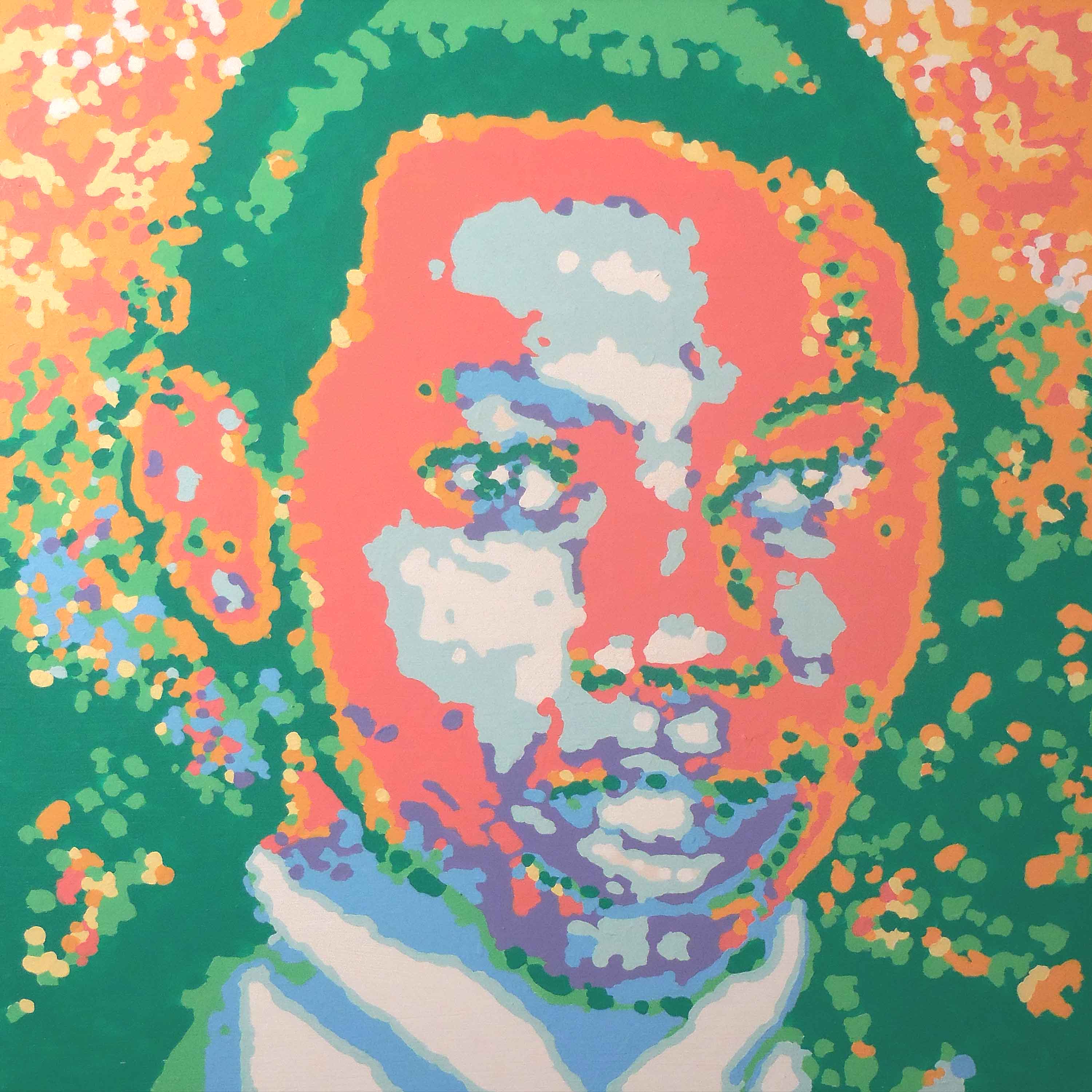
Timothy Thomas, Acrylic on board, 24" x 24", December 18, 2014
An idea for a robot never realized because programing became impossible without a mentor.
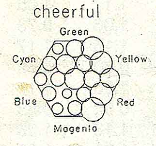
100604 Above is the graphic to generate from images. The size of the circle will match the number of pixels that color range. Tom painted for several years using this pallete.
100531 Able to sort pixels according to color using a shift register:)
Signed up for various LabVIEW get togethers in Cincinnati to keep his feet to the fire.
This is the go to place for learning: http://forums.ni.com/ni/board?board.id=460
Able to solve problems just by going through all the questions and answers.
Mr. Harris answered my question at: http://forums.ni.com/ni/board/message?board.id=460&thread.id=1449
NI Discussion Forums : Additional NI Product Boards : LabVIEW for LEGO MINDSTORMS NXT : loading sensor data into an array and then retrieving it
As Tom muddled through learning this fascinating language, his goal is to
be certified in LabVIEW in four years.
Next art-making robot will be a floating mobile where the arms float like a
mobile. Maybe it will paint with carbon smoke from a candle. Will be using Eric’s
Plotter from the Convict Boys School as a jumping off point to round up
all the line vectors.
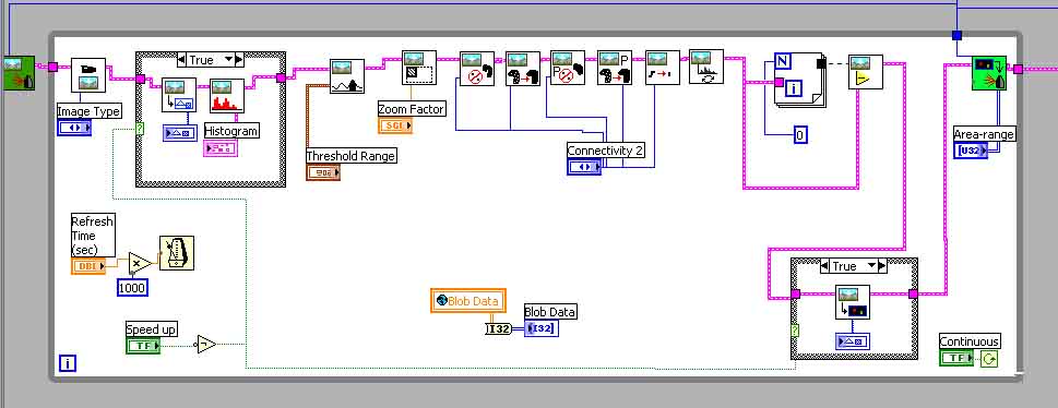
Current aesthetic image analysis vi. https://tomlohre.com/labview/100519.vi
It collects the total pixels that fit within certain parameters. Previous
robot distilled pixel information into eight colors. The initial image was posterized
into eight colors but in this vi may be able to receive images from the Lego
Camera of famous paintings and see what the spread of colors are in hope to
being able to discern a pattern.


100111
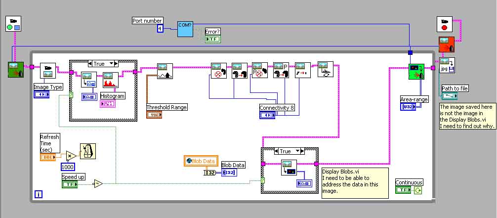
Adapting motionW.vi in the GPS_Camera8W.llb to display changes in the camera grab due to motion. Tom figuring out how to subtract an image from an image within the loop with the help of Chris at Tuffs University.
Trying to figure out how to save the black edge outline generated by motionW.vi in the second screen. If you save the image that comes out of the loop it is not image generated in the second screen.
In the above motionW.vi removing the beginning of the part of the program believing it will generate a motion outline. To get the outline making the connectivity 8.
http://www.convict.lu/Jeunes/ultimate_stuff/Erik_s_xy_plotter/E_xy_plotter.htm is an excellent stepping off point for my next painting Lego Robot. Using a precarious mechanical plotter like the one shown below because the machine does not have to be quick just elegant.
Able to adapt GPS8.vi in the GPS_Camera8.llb part of:
http://www.convict.lu/Jeunes/Robo_Soccer/Robo_Soccer2.htm
from Claude Baumann of the Convict School in Luxembourg to perform the Vision
Center process.
The program still has many things to work out but this is a real step forward
and consider it a Red Letter Day.
At this point the details of addressing the pixels and feeding the information
to the motors is not known but it should go rather quickly now.
Maybe by January the drawing robot will be operating and to start refining the
output.
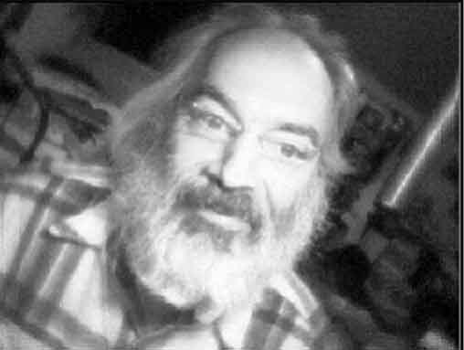
The first image is the raw image from the camera.
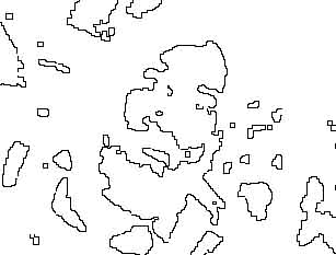
The second is the image derived in the program from the various processes: Threshold,
MorphOpen, MorphClose, MorphProperOpen, MorphProperClose, MorphThin and Invert
and finally using the Display Blobs.vi to create the second image.
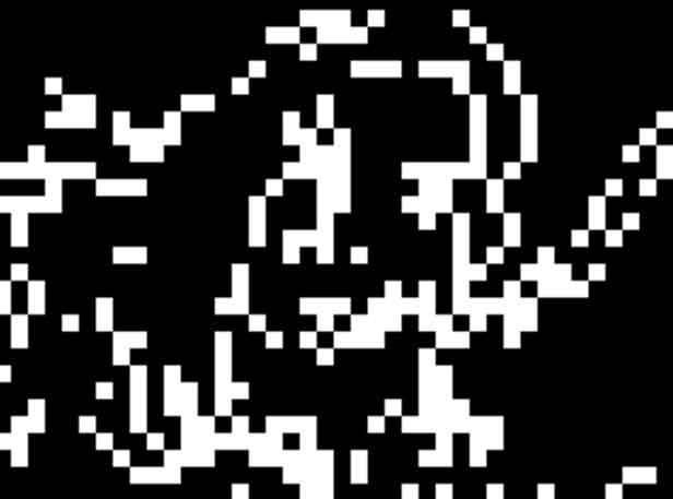
The last image is the image outputted with the save image command at the end
of the program. Sometimes the image is black and sometimes I can derive the
image out of it by isolating the levels to the area where the data is. There
is a discrepancy between the Display Blobs image and the saved image. The problem
now is addressing the individual pixels and feeding their location to a robot
printer made of Lego motors.
Trying to discover how to create a LLB.
110322 Working on the next painting automata. This one will be a floating mobile structure hooked up to a camera that looks for things to draw and then draws them. It may search the Internet to find images to draw. The searched images will be given a asthetic value number. The big challenge is to separate the colors of an image into little piles like the graph above. This will give a color number. Then to list the know objects in an image and quantify their value. Combining both number would give a aesthetic value number. The next big challenge is to build the floating mobile drawing device and coordinate it with the xy values from the image. The image will be distilled into short strings of coordinates that act as strokes. Using the new NXT brick to program this robot for it will allow complete use of LabVIEW programing. Will certainly need it to do the image processing.
161201 The next step is to make a smart phone app that searches the Internet for an image to paint then processes the image into a nine color. He learned that my making a machine to emulate the process of creation sheds light upon the process much like painting a copy of a masterpiece in a museum helps you learn technique.
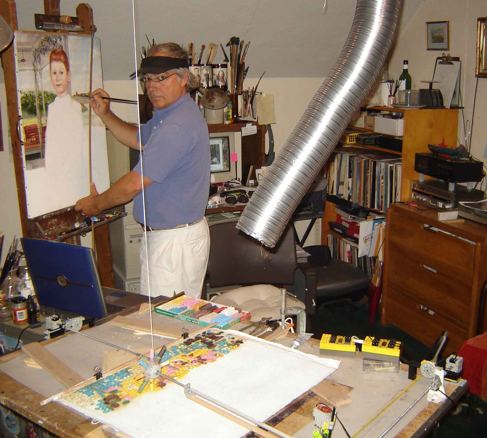
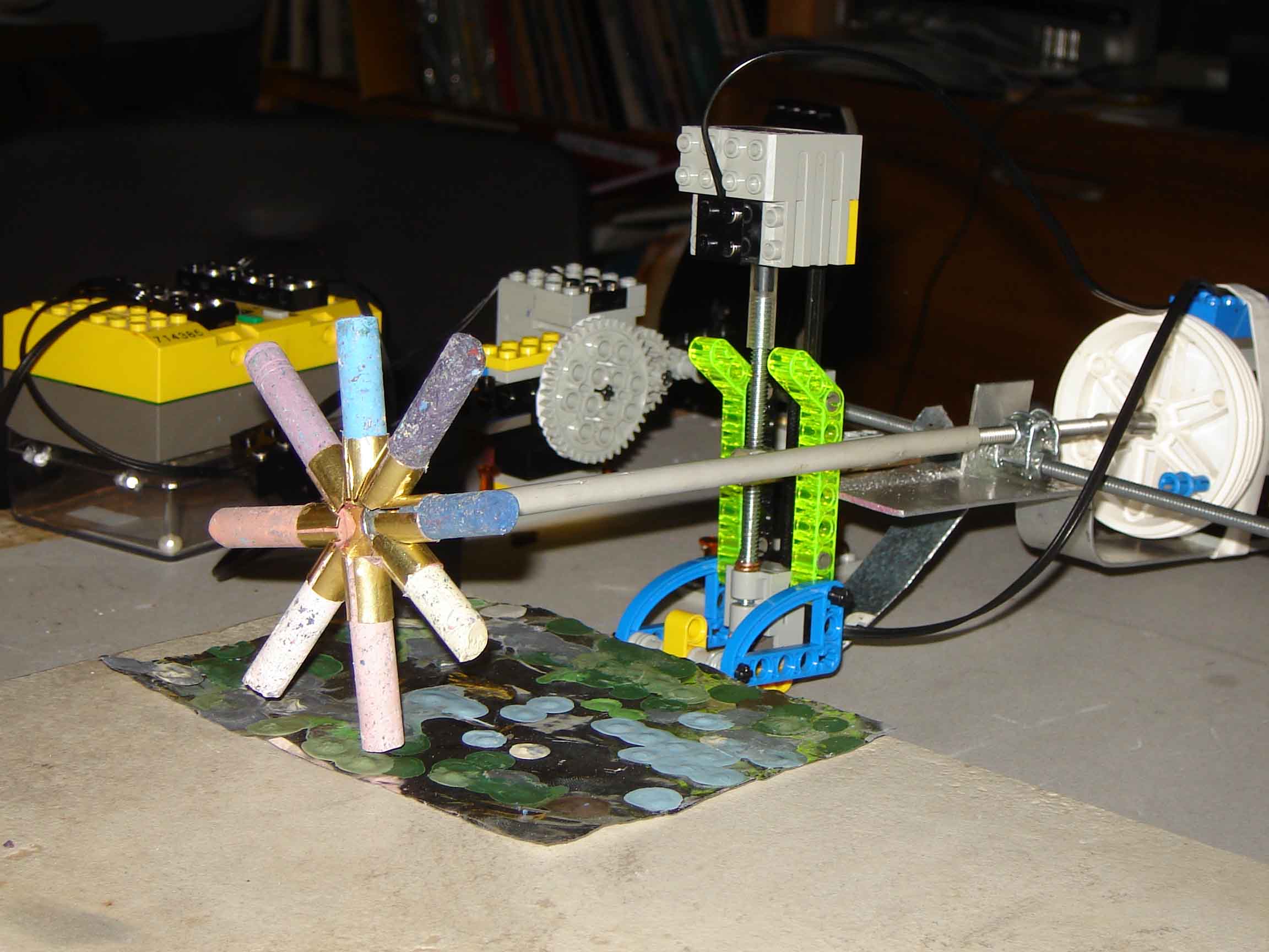
2007 Robot Artist
Made from Lego parts. The software is LabViews RoboLab.
The Cincinnati Post On-Line Story about the robot

Show of Lego Artisto's New Work January 2008
Complete Press Release: https://tomlohre.com/sitwell.htm
Sitwell's Coffee House, 324 Ludlow Ave., Cincinnati OH 45220, http://www.sitwells.net/, 513-281-7487
April Show of Art Work by Tom Lohre and a Lego Robot Assistant
Friday, April 18th to May 18th, 2008
Visual History Gallery, 1989 Madison Road Cincinnati, OH 45202, now
closed
The Story
In 1980 Tom started exploring the possibility of having a machine paint. He
had been painting impressionistic works one right after another and he got to
thinking he could make a machine to do this. In 2003 he discovered Lego's MindStorm
Robotic system and spent four years learning the software. On January 5th, 2007
at 9PM Tom finally cracked the code to write a program that took information
from an image in the computer and fed it to a painting machine.
The painting machine is like a classical assistant. It lays one of eight colors
in generally the correct spot and Tom manipulates it to refine its placement.
Tom initially creates an image in the computer that the machine follows. The
painting process takes 18 hours for a 16” x 20” having 4163 dots.
Tom can turn the machine off while working on a painting so the painting does
not have to be done all at one time. All the paintings in the Visual History
Show close ups of faces because the resolution is so low that he has to rely
on the viewer to fill in the blanks.
In the future, Tom sees the machine having 16 colors to select from with Tom working closely to continually adjusting the paint as it is laid down.
Link to the paintings in the show: https://tomlohre.com/newart.htm

2004 Robot Artist
In the past he has used a sweeping manner to cover the surface. The painting machine was guided by pushing buttons to make incremental motion to move to the next sweep in a unpainted area. The sensor would raise the print head when needed.